Home
BJT
single stage amplifier designing
FET single stage amplifier designing
BJT multistage amplifier designing
Power amplifier designing
Solved problems
Do not write text included in square bracket
Power transmitted to load, PL' = PL/nt
[nt = efficiency of transformer]
[If nt is not given assume nT = 90% or 0.9]
Q = (Pq max)/PL') = 2
[calculate Pq max]
Select transistor with Pd > 2 * Pq max
[Usually select ECN 149]
Vceq = Vcc - Vre
[calculate Vceq]
Vce peak = Vceq - Vce sat
[calculate Vce peak]
Ic peak = (2 * PL')/Vce peak
[calculate Ic peak]
Icq = Ic peak + Icmin
Assume Ic min = 0
[calculate Icq]
Pre = sqr(Vre)/Re
[Select power rating of Re > (2 * Pre). Specify power rating as multiple
of 0.25 W]
Ce = 1/(2 * pi * FL * RL)
[If FL is not given assume FL = 50 Hz]
Since Ce is very high we leave Re unbypassed
s = (1 + hfe max)/(1 + ((hfe max * Re )/(Rb + Re))
Find Rb[Do not standardise]
Vr2 = Vbe + (Icq * Re)
Vr1 = Vcc - Vr2
Assume Vbe = 0.6V [for Si, 0.3 for Ge if not specified]
R1/R2 = Vr1/Vr2 .............(A)
[Get R1 in terms of R2 & substitute in Rb]
Rb = R1 parallel R2 = (R1 * R2)/(R1 + R2)
Find R2
Select lower standard value to make circuit indepent of beta
Substitute in (A) to find R1
Select higher standard value so that circuit draws minimum current
from supply
RL' = (sqr(N1/N2)) * RL
[calculate (N1/N2)]
Select audio frequency transformer with turns ratio 1:(N1/N2)
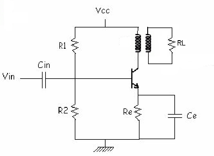
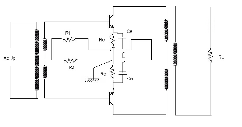
[Draw the circuit diagram with calculated values]
PL' FL = (Vce peak * Ic peak)/2
Pi dc = (Vcc * Icq) + (Vcc ^ 2)/(R1 + R2)
Half load efficiency, n HL = (PL' HL)/(Pi dc)
PL' HL = PL' FL / 2
Max power dissipation = power dissipation at no signal = Pd max of transistor
Q = (Pq max)/PL') = 1/5
[calculate Pq max]
Select transistor with Pd > 2 * Pq max
[Usually select ECN 149]
Vre = Vcc/10
[calculate Vre]
Vceq = Vcc - Vre
[calculate Vceq]
Vce peak = Vceq - Vce sat
[calculate Vce peak]
Ic peak = (2 * PL')/Vce peak
[calculate Ic peak]
Icq = Ic peak + Icmin
Assume Ic min = 0
[calculate Icq]
Idc full wave = (2 * Idc peak)/pi
Idc half wave = Idc peak/pi
Pre = sqr(Vre)/Re
[Select power rating of Re > (2 * Pre). Specify power rating as multiple
of 0.25 W]
Ce = 1/(2 * pi * FL * RL)
[If FL is not given assume FL = 50 Hz. Select higher std value]
s = (1 + hfe max)/(1 + ((hfe max * Re )/(Rb + Re))
Find Rb[Do not standardise]
Vr2 = Vbe + (Idc half wave * Re)
Vr1 = Vcc - Vr2
Assume Vbe = 0.6V [for Si]
R1/R2 = Vr1/Vr2 .............(A)
[Get R1 in terms of R2 & substitute in Rb]
Rb = R1 parallel R2 = (R1 * R2)/(R1 + R2)
Find R2
Select lower standard value to make circuit indepent of beta
Substitute in (A) to find R1
Select higher standard value so that circuit draws minimum current
from supply
RL' = (sqr(N1/N2)) * RL
[calculate (N1/N2)]
Power rating of primary > PL'
Select audio frequency transformer with turns ratio 1:(N1/N2)
[Draw the circuit diagram with calculated values]
PL' FL = (Vce peak * Ic peak)/2
Pi dc FL = (Vcc * Idc FW) + (Vcc ^ 2)/(R1 + R2)
Half load efficiency, n HL = (PL' HL)/(Pi dc HW)
Pi dc HW = (Vcc * Idc HW) + (Vcc ^ 2)/(R1 + R2)
PL' HL = PL' FL / 2
Top
Standard values